coal based power plant process flow diagram

Process simulations of postcombustion CO2 capture for coal and natural ...

Process simulations of postcombustion CO2 capture for coal and natural ...

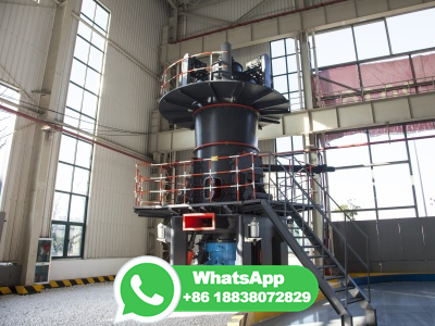
Fig. 1 illustrates the block flow diagram (BFD) of the conceptual flow sheet of a typical 550 MWe supercritical PC fired power plant integrated with a solid adsorbent based CCS system (adapted from NETL, 2010).After the flue gas passes FGD where SO 2 removal is carried out, it is directed into the CCS system instead of entering the stack directly as for the case of a power plant without CO 2 ...

Schematic diagram of a coalfired steam power plant [11]. ResearchGate

Schematic diagram of a coalfired steam power plant [11]. ResearchGate

The fossil fuel employed in a steam turbine plant can be pulverized coal (PC), oil, or natural gas. Of these, coal is the most abundant and hence the most commonly used fuel for steam turbine ...

Analysis of retrofitting coalfired power plants with carbon dioxide ...

Analysis of retrofitting coalfired power plants with carbon dioxide ...

The coalfired power plant Figure 1 shows the process flow diagram of the coalfired power plant. The basis of the analysed coalfired power plant is provided by the concept study “Reference power plant North RhineWestphalia†[1] which currently presents the stateoftheart of hard coalfired power plants in Germany with a net ...

Flow diagram of coalbased methanol production. ResearchGate

Flow diagram of coalbased methanol production. ResearchGate

Figure 2 shows a typical coalbased methanol production process (MC), which can be divided into two subsystems: a fresh gas preparation subsystem (to produce fresh gas for methanol synthesis from ...

Integrated Gasification Combined Cycle Power Plant

Integrated Gasification Combined Cycle Power Plant

The Kemper County IGCC power plant consists of two islands, the gasification island and the power island. Fig. shows a simplified block flow diagram of the overall process for easy reading; whereas, a more detailed block flow diagram is displayed in Fig. The overall layout characteristics of the facility include:

Simplified process flow diagram of the coalfired power plant (see ...

Simplified process flow diagram of the coalfired power plant (see ...

Context 1 ... process flow diagram of the coalfired plant is shown in Figure 3. The plant has a regenerative feed water system. ... View in fulltext Context 2 ... are three exit ports...

Schematic diagram of coal power plant. ResearchGate

Schematic diagram of coal power plant. ResearchGate

Context 1 ... schematic flow diagram of a pulverized coalfired power plant is presented in Figure 1. The power plantʹs operation can be explained in two, airflue gas cycle...

Coalfired power station Wikipedia

Coalfired power station Wikipedia

A coalfired power station or coal power plant is a thermal power station which burns coal to generate electricity. Worldwide there are over 2,400 coalfired power stations, totaling over 2,000 gigawatts capacity. [1] They generate about a third of the world's electricity, [2] but cause many illnesses and the most early deaths, [3] mainly from ...

: Mining, Processing, and Generating Electricity

: Mining, Processing, and Generating Electricity

Oil is occasionally used to generate electricity as well. Figure n : This combustion chamber burns either natural gas or oil. Fuel flows through a natural gas line or from oil storage into the combustion chamber. Air passes through the air intake and is compressed in the compressor.

PDF HOW ELECTRICITY IS PRODUCED AT A COALFIRED POWER STATION ... Eskom

PDF HOW ELECTRICITY IS PRODUCED AT A COALFIRED POWER STATION ... Eskom

sufficient coal reserves available to keep the power station in operation should the mine experience production problems. Inside the power station, the coal is pulverised to a fine powder in giant grinding mills. This is because pulverised coal burns quickly, like gas. The pulverised coal is transported to the boiler furnace with air where it ...

PDF Coal Cleaning US EPA

PDF Coal Cleaning US EPA

Typical coal cleaning plant process flow diagram. (Source Classification Codes in parenthesis.) EMISSION FACTORS 11/95. The major emission source in the fine or coarse coal processing phases is the air exhaust from the air separation processes (air tables). For the dry cleaning process, these emissions are generated

Causal analysis of nitrogen oxides emissions process in coalfired ...

Causal analysis of nitrogen oxides emissions process in coalfired ...

Coalfired power plant. This study focuses on a coalfired power plant with a 700 MW supercritical tangential firing boiler built in the Kansai region of Japan and is operated using mixtures of various types of coal in consideration of economic efficiency. Figure 1 shows a schematic diagram of the overall system configuration (Zhang. (2013)).

Modeling and Evaluation of a Coal Power Plant with Biomass ... IntechOpen

Modeling and Evaluation of a Coal Power Plant with Biomass ... IntechOpen

The results indicate that cofiring 10% of biomass in a coalbased power plant only slightly affects the energy performance of the plant, reducing the net efficiency by % points. ... A simplified process flow diagram of the MEAbased chemical absorption process for CO 2 capture used in this study is shown in Figure 4.

Oxyfuel combustion for CO2 capture in power plants

Oxyfuel combustion for CO2 capture in power plants

The application of oxyfuel combustion for coal fired power plant could be broadly classified according to: (a) oxyPC and (b) oxyCFB. On the other hand, the application of oxyfuel combustion for gas turbine based power plant could be broadly classified according to its working fluid namely: (a) CO 2 based GT cycles and (b) Water based GT cycles.

Modeling and simulation of the startup process of coal fired power ...

Modeling and simulation of the startup process of coal fired power ...

Simplified process flow diagram of the water steam cycle of a power plant (Wellner et al., 2016). ... The modeled power plant is based on the coal fired single block supercritical power plant with a 920 MW gross electric output located in Heyden, Germany. During the modeling process, several simplifications were made to allow for a fast ...

PDF STANDARD DESIGN CRITERIA/ GUIDELINES FOR BALANCE OF PLANT OF 2 x (500MW ...

PDF STANDARD DESIGN CRITERIA/ GUIDELINES FOR BALANCE OF PLANT OF 2 x (500MW ...

CEATETDCHP001 Typical coal flow diagrams for 2 x 500MW thermal power plant (with ... A coal based thermal power plant consists of large number of integrated plants/systems and equipment having mechanical, electrical, instrumentation control and civil components. The plant systems and equipment can be broadly classified into following

Thermal Power Plant: Diagram, Layout, Working Construction

Thermal Power Plant: Diagram, Layout, Working Construction

The thermal power plant is essential to maintaining the supply of electricity because it can adapt quickly to changes in demand. A thermal power plant, also known as a thermal power station, is used to transform heat energy into electric power for domestic and industrial applications. Electric power is generated by steampowered turbines, which ...

ISO 140841:2015(en), Process diagrams for power plants ? Part 1 ...

ISO 140841:2015(en), Process diagrams for power plants ? Part 1 ...

1 Scope. This part of ISO 14084 specifies types of process diagrams for power plants and rules and guidelines for the preparation and representation of information in such diagrams. This part of ISO 14084 series is a collective application standard of the ISO 15519 series. This part of ISO 14084 does not apply to electrotechnical diagrams ...

Point Source Carbon Capture from Power Generation Sources

Point Source Carbon Capture from Power Generation Sources

Point source capture (PSC) in fossil fuelbased power production separates CO 2 emissions from a power plant's flue gas or syngas stream to prevent its release into the atmosphere. The captured CO 2 is durably stored or converted to a longlived product, resulting in an overall reduction in CO 2 emissions. In conventional fossil fuelfired power plants, a fossil fuel such as natural gas is ...

Predictive modeling of a subcritical pulverizedcoal power plant for ...

Predictive modeling of a subcritical pulverizedcoal power plant for ...

Model validation was done but only over a small load range, from full to 88% load, by comparing only a few key process variables, namely coal flow, steam flow, and plant efficiency. Chen et al. [9] and Chen and Bollas [13] used the Dymola simulation environment and Thermal Power Library to build a dynamic model of a subcritical plant.

PDF K22: Full Chain Process Flow Diagrams

PDF K22: Full Chain Process Flow Diagrams

Carbon Capture and Storage A technology which reduces carbon emissions from the combustion based power generation process and stores it in a suitable location ... Process Flow Diagram Process Flow Diagram (PFD) is a drawing which describesthe process flow for a processing plant. PFD is used to capture the main process equipment

Development of multimode gasfired combinedcycle chemical ... Springer

Development of multimode gasfired combinedcycle chemical ... Springer

A process flow diagram of the proposed power plant layout is shown in Fig. 10. Based on mass and energy balances discussed in the "Layout of natural gasfired pressurized CLC" and "Layout of syngas fired pressurized CLC" sections, this has been developed for a 761 MW th plant when fired with natural gas and 800 MW th when fired with ...

PDF Power Generation from Coal

PDF Power Generation from Coal

Coal is the biggest single source of energy for electricity production and its share is growing. The efficiency of converting coal into electricity matters: more efficient power plants use less fuel and emit less climatedamaging carbon dioxide. This book explores how efficiency is measured and reported at coalfired power plants.

Gas Turbine Power Plant: Diagram, Working Types [PDF]

Gas Turbine Power Plant: Diagram, Working Types [PDF]

Advantages of Gas Turbine Power Plant with Nuclear Power Plant. The following are the advantages of a gas turbine power plant with a nuclear power plant: Low weight and size: wt of the plant per kW output is low. Any hydrocarbon fuel from highoctane gasoline to heavy diesel oil can be used efficiently. Easy startup and shutdown.

Coalfired power plant process diagram. ResearchGate

Coalfired power plant process diagram. ResearchGate

Coalfired power plant process diagram. | Download Scientific Diagram Content may be subject to copyright. Coalfired power plant process diagram. Source publication +20...

How a Coal Plant Works

How a Coal Plant Works

How a Coal Plant Works. Coalfired plants produce electricity by burning coal in a boiler to produce steam. The steam produced, under tremendous pressure, flows into a turbine, which spins a generator to create electricity. The steam is then cooled, condensed back into water and returned to the boiler to start the process over. Here's a real ...

Advanced Process Control for Optimizing Flue Gas Desulfurization

Advanced Process Control for Optimizing Flue Gas Desulfurization

Figure 1 depicts a flow diagram for a typical wet ... savings at another 1,000MW coalfired power plant in Japan as well. ... multiple techniques including modelbased prediction, process value ...

Flow diagram of the coal fired power plant ResearchGate

Flow diagram of the coal fired power plant ResearchGate

Jun 2015 Mirjana Lakovic Milos Banjac Milica Jovcevski Dejan Mitrović Abstract. Coalfired power plants emit large amounts of CO2, which constitutes one of the largest causes of global...

Coal Handling Plant In Thermal Power Plant

Coal Handling Plant In Thermal Power Plant

The initial process in coal based thermal power plant is coal Function of coal Handling Plant in thermal power plant is to receive, process, store, feed the coal bunkers consistently over entire life of the power plant. Coal is transported in thermal power station either by railways,roadways or rope ways.

PDF Technical Manual for the SAM Biomass Power Generation Model

PDF Technical Manual for the SAM Biomass Power Generation Model

a coalfired power plant or cofired plant. ... solar water heating system) based on userspecified inputs describing a system's physical configuration, its location, and the cost of installing and operating the system. SAM's ... Biomass power process flow diagram . 3

How to design Coal Power Plant Process Diagram in PowerPoint ... YouTube

How to design Coal Power Plant Process Diagram in PowerPoint ... YouTube

Animation for the above schematic is available at the following link. (https:///VcDPFWGXKeY) Making process diagrams and attractive too can be a mind...

Coalfired power generation | Sulzer

Coalfired power generation | Sulzer

Coal and oilfired process. Coal and oilfired steam power plants have steam turbines to convert the heat energy of combustion into mechanical energy, which then operates an electric generator. All plants use the steam turbine for the drop between the high pressure and temperature of the steam and the lower pressure of condensing vapor.

A CoalFired Thermoelectric Power Plant | Geological Survey

A CoalFired Thermoelectric Power Plant | Geological Survey

As this diagram shows, the plant operates on the same principles as other fossilfueled electric generating plants—it burns coal to produce heat that turns water into steam, which then turns turbines in a generator. Sources/Usage: Public Domain. Credit: Georgia Power

Integrated gasification combined cycle Wikipedia

Integrated gasification combined cycle Wikipedia

Below is a schematic flow diagram of an IGCC plant: Block diagram of IGCC power plant, which utilizes the HRSG The gasification process can produce syngas from a wide variety of carboncontaining feedstocks, such as highsulfur coal, heavy petroleum residues, and biomass .

PDF Power plant process flow diagram

PDF Power plant process flow diagram

Power plant process flow diagram A thermal power generating plant works based on Rankine Sugar. There are mostly three main inputs provided in a power generating thermal plant for producing electricity. The three most essential components are coal, air, and water. Coal is gas here because we are going to draw the flow diagram to a thermal coal ...

دریافت اطلاعات بیشتر